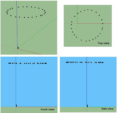
In magnetometer calibration mode, when the button is pressed, 16 consecutive MicroMag3 raw measurements are sent to the serial port. A remote laptop running Hyperterminal continually saves these measurements in a text file. The compass assembly is rotated step by step around the X axis and measurements are taken after each small rotation. Then the procedure is repeated around the Y axis.
The following figure illustrates the first set of measurements taken with this arrangement, as rendered in Google Sketchup.
The compass base is then placed completely horizontal, and a set of measurements are made by rotating the compass assembly around the Z axis. The following figure illustrates the measurements taken with this arrangement, as rendered in Google Sketchup.
For each of these raw measured points (mrx, mry, mrz), we calculate their calibrated values (mx, my, mz).
We now want to find the equation of the plane (ax + by + cz + d = 0) that best fits these calibrated points. Using the NLREG software, we find the following equation parameters:
a = 0.0125592224
b = 0.00391778749c = 1
d = -3166.69898
The vector normal to the plane (vector v3) is then (a, b, c)
= (0.0125592224, 0.00391778749, 1) with a calculated norm of 1.000087.
This vector represents the orientation of the magnetometer reference frame in the rigid base reference frame.
= (0.0125592224, 0.00391778749, 1) with a calculated norm of 1.000087.
This vector represents the orientation of the magnetometer reference frame in the rigid base reference frame.
We can thus conclude that when the orientation of the magnetometer reference frame in the gravitational field is v3 = (0.0125592224, 0.00391778749, 1), then the orientation of the rigid base in the gravitational field is v2 = (0.0, 0.0, 1.000087).
From the values of vectors v2 and v3, it is now possible to calculate the rotation matrix that can be applied to any vector v2 (orientation of the rigid base in the gravitational field) to get the associated vector v3 (orientation of the magnetometer reference frame in the gravitational field):
We will also need this rotation matrix later on for the tilt compensation corrections.


I'm doing a similar project.
ReplyDeleteHere are some observations, questions.
1. It would be interesting to reverse engineer the angles out of the rotation matrix.
2. Calibration. I notice doing the calibration on my chip, that I occasionally get outliers. So I think a two state calibration might improve things. First the calibration to get the initial results. Second, cull the outliers and then recalibrate.
3. The numbers feed into the calibration aren't equally distributed. So you will get a bias. I think equally spaced samples might make difference.
4. It's hard to completely calibrate in situ. For example, you can't turn your boat completely inverted (or perhaps you can!). The bias for hard and soft iron isn't going to be accurate from just calibrating the instrument in isolation.
So I'm looking at creating equal areas on a sphere. Sampling say 10 readings per area, and using those for the calibration. I think I can get that done quick enough for a small processor, certainly for an arduino mega.
Tesselate the sphere off line, creating the data. Find the nearest point (tricky to do it quickly), and add the sample to the bucket. When the buckets are full, calculate the A and/or A inverse, B matrix, and store)
5. Inputing magnetic declension and inclination for the location. (Another rotation on the result)
6. Calibrating the installation (Another rotation). Here I'm looking at putting one in a sailplane. Moving environment makes it even more difficult, plus the angle of attack varies with speed and wingloading (weight + g loading)
I find the whole thing quite an interesting intelectual challenge.
Thanks for sharing your toughts, Lord Blagger.
Delete1. I will have a look at this and report later.
2. I agree that ouliers should not be part of the calibration data. When I get outliers, I reject the whole calibration run and start again.
3. Agreed for the principle. For the calibration of my hi-resolution compass, I now rotate the compass around 3 mutually perpendicular axis (instead of 2 in the example above this post). I have added wheel markers at the end of the shaft to get equal angles. I think that the ellipsoid is pretty well defined in this manner and that taking more data will have a diminishing return value. More on that later on.
4. Agreed. My approach is to get a the best isolated calibration before putting the compass on the boat, and then look for additional hard and soft iron corrections, using the GPS to check if additional deviation corrections are needed, and heeling the boat manually to check if additional tilt compensation corrections are needed.
I like your bucket idea for the magnetometer calibration. I can get good repeatable calibration results by just rotating very slowly by hand the compass in all directions, and then processing the data. Bucket filtering of the data will improve these results further. (This is not possible for the accelerometer calibration, as each measurement shall be made after the chip has been perfectly still for several seconds, with no vibration from the environment).
5. In my case, when I need to translate from true heading to magnetic or the other way, I just use a fixed variation correction that I adjust at the beginning of the sailing season.
6. I am lost on this one.
"I find the whole thing quite an interesting intelectual challenge".
Agreed.
5. In my case, when I need to translate from true heading to magnetic or the other way, I just use a fixed variation correction that I adjust at the beginning of the sailing season.
Delete========
The combination of declination/inclination and installation adjustment is obviously combined as one adjustment. However, if you move large distances, then the installation adjustment should be constant, but the declination/inclination will change.