First, we need to find the orientation of the magnetometer reference frame (ax, ay, az) in the gravitational field.
This is given by:
The 3 correction matrices and the 3 bias values have been established during the calibration process. The 3 matrices can be pre-multiplied in order to simplify future calculations. For the example presented in the last 2 posts, the equation reduces to:
We then normalize this result:
We now calculate the calibrated magnetometer values (mx, my, mz):
For the example presented in the last 2 posts, we have:
And finally, the tilt compensated heading is given by:
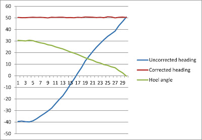
In the following example, the compass base is tilted on its side to produce a heel angle of around 30 degrees, and then slowly comes back to horizontal, as shown by the green curve. This produces a huge variation in the uncorrected heading (the blue curve). The tilt compensation does an excellent job, as the red curve is truly horizontal.
To see the improvement of the calibration, compare with the similar example appearing in this older post.


No comments:
Post a Comment