Friday, October 28, 2016

Live GPS Tracking for Club Regattas (Step 1)

Live GPS tracking is already a standard feature at major sailing events.


 Each contestant is provided with a GPS tracker that communicates wirelessly with some remote station. Three technologies are being used for the transmission of data: satellite, GPRS (cellular) and UHF radio.

  • Satellite communication is used for offshore racing and will not be discussed here.


  • GPRS requires cellular coverage in the race area, and individual SIM card and mobile phone plan for each tracker. It is extensively used in a wide range of sporting events. An exemple of GPRS in sailing is the TracTrac offering. Here is a picture of their tracker and charging units:


  • UHF radio links are more flexible, but apply to shorter ranges, typical of what we find in local club events. This is what has been used in the recent Rio Olympics sailing events, with Swiss Timing as the technology provider. Here is picture of their tracker and charging units:


Application to club sailing events

I have been looking at a way to bring GPS tracking to local sailing clubs, along the following parameters.

- all boats are always within 1.5 nautical mile of the committee boat
- the committee boat is within 5 nautical miles of the clubhouse
- each boat reports its position, speed and heading at short intervals (1 second typical)

For the last parameter, the data (GPS position, SOG and COG) can all be incoded in 9 bytes. For example, the following NMEA sentence from the GPS:
              
               $GPRMC,180846.600,A,4659.8765,N,07058.4321,W,12.00,270.00,050210,,,D*77

can be sent as 4 integers:  598755 (Longitude, 3 bytes), 584321 (Latitude, 3 bytes), 120 (SOG, 1 byte) and 2700 (COG, 2 bytes).

In this post, we look at the communication between the committee boat and the contestant boats, in order to provide a live display of the race in the committee boat. Communication with the clubhouse and the live broadcasting of the event on the internet will be discussed later. 


Preferred technology: LoRa radios in the 915 MHz band

“Long Range (LoRa)” packet radios appear well suited to meet the objectives of this kind of project. For range tests, I have used 2 Adafruit Feather M0 RFM95 radios, featuring a Semtech LoRa transceiver.


Technical details can be found in the following in Semtech’s LoRa Modem Designer’s Guide.

Semtech also provides a useful LoRa Calculator Tool, under the tab ‘Docs & Resources’.

The Semtech tool can be used to calculate the ‘Time on Air’ required to transmitting the 9 bytes packets. In the following example, the LoRa radio is configured with the following settings:
- Spreading Factor : 6
- Bandwidth : 125 kHz
- Coding Rate : 4/5
- No Explicit Header


For these conditions, the ‘Time on Air’ is 18.04 ms, with an equivalent bitrate of 9375 bps. This means that up to 50 boats could be sampled each second for their position, COG and SOG from a single transceiver on the committee boat.


LoRa range tests

Two prototype transceivers have been assembled to test the communication range over water. The Adafruit modules have been programmed with the RadioHead software recommended on the Adafruit site.


With a 3 dBi half-wave dipole antenna in each module (as shown above), reliable communications have been obtained up to 1.75 nautical mile, with spotty communications up to 1.9 nautical mile. With simple wire antennas, the reliable range is reduced to 0.75 nautical mile. With a higher gain antenna on the committee boat transceiver (like 6 dBi), the range could be further extended, or the antenna gain on the trackers could maybe be relaxed, allowing smaller antennas.

These tests thus confirm the feasibility of the LoRa approach.


Further steps

The next steps that are being considered are  :

-   to build a small inventory of waterproof trackers, and develop an application to visualise the boat positions aboard the committee boat

-  to develop the communication link between the committee boat and the clubhouse (GPRS cellular network or more powerful radio)

- from the clubhouse, to broadcast the live data on a web site, allowing display on local TV set and any mobile device.
  

Thursday, April 14, 2016

Building your own NMEA 2000 Device

The hard work has already been done, first by the pioneering efforts of Kees Verruijt at canboat , and now by the development of a NMEA2000 Arduino library by Timo Lappalainen.


I am using the NMEA2000 library with an Arduino Due board. The Due has a built-in CAN controller (in fact 2 of them), missing only an external CAN transceiver to get attached to a N2K backbone. With the arrangement described below, I first ran the library example ‘TemperatureMonitor’, sending 2 fixed temperature values to the N2K network. The result can be seen in the following screen capture of the B&G Touch 7 display, showing the sea and cabin temperature values sent by this example.


I then proceeded to develop a replacement for the Actisense NGW-1, which translates fast NMEA 0183 heading sentences to their equivalent N2K PGN. For this, I also made use of the TinyGPS++ library, which takes care of parsing the NMEA 0183 sentences. 


All this is done with a deceptively short Arduino sketch (‘Heading Converter’), which I reproduce in its entirety here.

// Convert fast heading data from NMEA 0183 to NMEA 2000

#include <Arduino.h>
#include <NMEA2000_CAN.h>
#include <N2kMessages.h>
#include <TinyGPS++.h>

TinyGPSPlus gps;
TinyGPSCustom heading(gps, "HCHDG", 1); // $HCHDG sentence, 1st element

void setup() {
  Serial2.begin(9600);
  
  NMEA2000.SetProductInformation("00000001", 100,"Heading converter", "1.0.0.11 (2016-04-13)", "1.0.0.0 (2016-04-13)");
  NMEA2000.SetDeviceInformation(1, 140, 60, 2046);
  NMEA2000.SetForwardOwnMessages();
  NMEA2000.SetMode(tNMEA2000::N2km_NodeOnly,22);
  NMEA2000.EnableForward(false);
  NMEA2000.Open();
}

void loop() 
{
  tN2kMsg N2kMsg;
  if (heading.isUpdated())
  {
    SetN2kMagneticHeading(N2kMsg, 1, DegToRad(atof(heading.value())));
    NMEA2000.SendMsg(N2kMsg);
    NMEA2000.ParseMessages(); 
  }
  
  while (Serial2.available() > 0)
    gps.encode(Serial2.read());
}

Tuesday, April 5, 2016

NMEA 2000 for Radar Overlay

Radar overlay means displaying the radar image directly on the chart. This is a nice feature to have with the 3G radar, as it also permits to experiment with MARPA. But it complicates somewhat the installation, as it requires sending 10 Hz heading values to the radar through a NMEA 2000 network. So here is how I ended doing it.


As explained in my last post, I was already sending the NMEA 0183 HDG sentence directly to the Zeus T7 display, among other NMEA 0183 sentences (VHW, MWV, and MWD). I have now isolated the HDG sentence to a separate serial port, and sending it at 10 Hz to an Actisense NGW-1, which converts it to the equivalent N2K 127250 PGN (Vessel Heading), now available both to the T7 display and to the radar through my basic N2K network.

Other than the Actisense NGW-1, there are 2 other options to make the heading conversion from NMEA 0183 to N2K:
               - using the Navico AT10 HD converter;
               - using a DIY converter based on the Arduino Due board (more on this in a future post).

The Actisense NGT-1 is used to monitor the N2K network. It confirmed that the 127250 PGN is effectively transmitted at the required 10 Hz rate.

The WIFI-1 router is used to remotely view and control the display from a phone or tablet. It also broadcasts the most common NMEA 0183 sentences that the display makes available on the Ethernet network (also more on this later).

Sunday, January 31, 2016

Interfacing a B&G Zeus Touch 7 Display

I am planning the installation of a B&G Broadband 3G radar, using a Zeus Touch 7 (T7) for display. I have now received the display that will also act as a chartplotter. So it was natural for me to check if I could use the T7 Sailsteer feature, by using my own data.

It happens that the T7 has an input for NMEA0183 data. My system produces a 10 Hz stream of binary data that I have to convert to NMEA sentences supported by the display. The conversion is done by a SAMD21 32-bit microprocessor, connected to the display through a MAX3232 converter. Note that the T7 has its own internal GPS, so that I don’t need to convert and send the GPS data from my system.

Here is the schematics and wiring used. Each NMEA sentence is sent once per second, through the NMEA 0183 Talker port (orange and green wires), using a baud rate of 38400.


To test the behaviour of this setup, I used an example presented in an earlier post. I reproduce here the data from this example for convenience.


As a first test (System A of the example), I send continuously the 4 following inputs:

Heading : 0.0 deg  
Boat Speed : 6.0 knots
Apparent Wind Angle (AWA) : -26.71 deg   (-26.71 + 360 = 333.29)
Apparent Wind Speed (AWS) : 16.43 knots
     $HCHDG,0.0,,E,,W*50
     $IIVHW,,T,,M,6.0,N,,K*7D
     $WIMWV,333.29,R,16.43,N,A*1B

This corresponds to the basic inputs that the display would receive if it was directly connected to sensors (masthead unit, speed log and electronic compass). So the display is left calculating the following outputs: TWA, TWS, VMG and tide current. Here is a screen capture of the display for these conditions.


The calculated outputs of the display correspond exactly to those of the basic System A example. It is interesting to note that the display has correctly calculated a front current of 6 knots, as its GPS gives him a 0.0 knot SOG (the test is made at home, and the home does not move!).

But we know from the example that these results suffer from 2 problems: the AWA is not corrected for heeling, and the leeway is not considered. In the second test (System B), I send instead the AWA  corrected for heeling (available from my system).


Heading : 0.0 deg  
Boat Speed : 6.0 knots
Apparent Wind Angle (AWA) : -28.17 deg   (-28.17 + 360 = 331.83)
Apparent Wind Speed (AWS) : 16.43 knots
     $HCHDG,0.0,,E,,W*50
     $IIVHW,,T,,M,6.0,N,,K*7D
     $WIMWV,331.83,R,16.43,N,A*19

Here again, the values calculated by the display agree with the results of the example for System B.


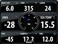
In the third test (System C, corrected for leeway), I send these additional inputs correctly calculated by my system (instead of letting the T7 make these calculations):

True Wind Angle:  -45.0 deg  (-45.0 + 360 = 315.0)
True Wind speed:  12.0 knots
Wind Direction: 315.0 deg
     $WIMWV,315.0,T,12.0,N,A*11
     $WIMWD,,T,315.0,M,,N,,M*73

I cannot send the result of my VMG calculation because the VPW NMEA sentence is not supported by the T7, so that the VMG calculation is left to the display.


Here we see that the VMG value is not calculated correctly by the display. This is not surprising as the display has no information on the leeway. To do so and to reproduce all the correct data, this system would have to be completed by the B&G H5000 computer.

But despite this problem that may somewhat affect the resulting calculated laylines, I expect that the Sailsteer feature will still be very useful in practice, as it takes in account the tide current values in its calculations. This is a much more important correction in my sailing area characterized by strong tidal streams.

For now, the erroneous calculated VMG value will not be displayed on the T7, to avoid confusion with the correct value displayed on my tablet.  


Thursday, January 8, 2015

Wi-Fi revisited with the ESP8266 chip

The new ESP8266 chip has created quite a buzz in the recent months, and I have decided to give it a try for Wi-Fi communications between my instruments and a Nexus tablet. The ESP8266 is a 3 $ chip that can be programmed as a Wi-Fi access point (AP) as well as as client for a router (STA) at the same time if required. It can even host a small Web server. An SDK (Software Development Kit) is available to configure the microprocessor to specific needs.

In my case, I use it as UDP server to send the serial output generated by my system. The UDP packets are sent at the 10 Hz rate, and contain a payload of 76 bytes (mostly measured and calculated values in floating-point format). The payload contents are described here. And how the calculations are made is described here.


The Nexus tablet is programmed as a UDP client, connected to the ESP8266 AP network visible to any Wi-Fi device. When the tablet software sends a ‘START’ message to the ESP8266, it is bombarded back by the 10 Hz packets until it sends a ‘STOP’ message. These data are used to refresh the displays in real-time on the tablet. Many different custom displays can be swapped around. Any resemblance to recent professional first-class displays is not coincidental: the Android graphics capabilities are impressive.

Here is the prototype arrangement used. The ESP8266 is a 3.3V device, and a logic level converter is used on the 5 V serial signal from the system.


For development with the SDK and programming, I used this Eclipse-based tool-chain, on a Win7 64-bit machine: Espressif DevKit for Windows.


Friday, August 22, 2014

A low-cost marine compass (Part 3 – Calibration)

When connected to a terminal program through the FTDI breakout at 115200 baud, the compass displays the results formatted as NMEA sentences. This is the default operating mode (Mode 4 in the software).

Two calibration helper modes are available:
        Mode 1 : Accelerometer  calibration (type M1<ENTER>)
        Mode 2 : Magnetometer calibration (type M2<ENTER>)

These calibration modes are used to produce the raw data files required by the calibration software Magneto. In these modes, the compass stops displaying results until it receives an ‘x’ character (type x<ENTER> in the terminal program).

In Mode 1 (Accelerometer), it will then displays 64 consecutive (x,y,z) filtered raw data (at the 200 Hz rate), then pauses until it receives another ‘x’ character.


In Mode 2 (Magnetometer), it will displays 16 consecutive (x,y,z) raw data (at the 6.5 Hz rate), then pauses until it receives another ‘x’ character.


By logging the results to a text file in the terminal program, it is then possible to create the Magneto input files, by moving the compass around and pressing the ‘x’ character at each new position.

I recommend moving the compass with roughly equal angle steps around three perpendicular axis. For the accelerometer, you can use any support (metallic or not) to help position the compass, but it is very important to wait until the compass is completely at rest (no vibration) before hitting the ‘x’ character.

For the magnetometer, try to use the lightest non-magnetic support (wood or plastic), and use the ribbon cable to keep away the FTDI brekout and especially the laptop (all this in a magnetic clean environment!).

The 2 raw data files can then be processed by the Magneto software. The Pro Mini source file can then be edited with the new values and recompiled.

Unfortunately, this is not the end of the game if we want to be rigorous. We will have to look for misalignments between three independent reference frames: the compass base, the accelerometer plan and the magnetometer plan, with a final offset correction when compared to a known heading.

But the compass should already be quite usable, as these last corrections will be quite small compared to what has been accomplished.


A low-cost marine compass (Part 1 - Hardware)
A low-cost marine compass (Part 2 - Software)


Wednesday, August 20, 2014

A low-cost marine compass (Part 2 – Software)

The problem with low-cost sensors is that the accelerometer outputs are very noisy (much less so for the magnetometer).

The LSM303D sensor is one of 2 magnetic sensors supported by the PX4 development team. The solution they have chosen to reduce the noise in the accelerometer outputs is to apply a low-pass software filter to the measurements, in addition to the hardware low-pass filter built into the chip. In this project, I have ported their LSM303D SPI driver and 2-pole software filter to the WinAVR environment.

I have also kept the strategy adopted for my Hi-Res compass, which is to use a higher sampling rate for the accelerometer, and take the average result in the calculation performed after each magnetometer measurement.

I have chosen a 6.25 Hz sampling rate for the LSM303D magnetometer, to insure that it will operate in its hi-resolution mode. The accelerometer sampling rate is set at 200 Hz, and the cut-off frequency of the software low-pass filter is set at 40 Hz.

Here is a general explanation of the code behaviour during normal operation.

The Pro Mini continually reads triple raw values (x,y,z) from the accelerometer. For each axis, it feeds the raw value to the software low-pass filter, which spits out a new filtered value for each axis. The filtered values are accumulated and counted.

Each time the LSM303D magnetometer has a new set of 3 raw values available (x,y,z), it fires an interrupt on the Pro Mini. When this happens, the Pro Mini applies the calibration correction to the magnetometer values. It calculates the average of the accelerometer filtered values since the last interrupt, and applies the calibration correction. From this set of 6 values, it calculates the tilt-compensated heading, and the heel and pitch angles. It formats the results in 2 NMEA sentences that are sent to the serial port (115200 baud), 6.25 times per second. 


The source code for the WinAVR environment can be found here. I am using Programmer’s Notepad to compile the code and program the Pro Mini through the Arduino bootloader. 

This implies that the calibration factors have already been found since they appear as constants in the code. The software has other modes of operation useful for developing these calibration factors, which will be presented in Part 3 of this series.


A low-cost marine compass (Part 1 – Hardware
A low-cost marine compass (Part 3 - Calibration