Saturday, November 19, 2011

Doppler profiler: design considerations

With a pulse-to-pulse coherent Doppler profiler, we can pick a specific remote region where we want the measurement to be made. Here we plan to measure the average speed of water in a sample volume of 1 cm long situated at 1 meter from the transducer.


With a speed of sound through water of 1500 m/s, the time to a first echo from the beginning of the sample volume is 1333.3 μs. The time to a first echo from the end of the sample is 1346.7 μs.

To make a measurement, the 3 MHz transducer will send 2 pulses.

After sending the first pulse, the transducer will switch to receive mode and will sample the echo from exactly 1333.3 to 1346.7 μs after the beginning of the pulse. The microprocessor will digitize this echo with its internal 84 MHz ADC and store it in memory. Soon after, the transducer sends a 2nd pulse and the process is repeated.  The second echo is also digitized and stored. As the particles in the water have moved between the 2 samples, the echoes will be separated by a phase angle ϕ (the Doppler shift).  From the stored data, the microprocessor will then calculate the Doppler shift (90 deg in the following figure).


The Doppler shift is related to the component of the speed of the water in the axis of the ultrasonic beam. But there is a problem: more than one velocity value will produce the same Doppler shift.


To pick the right one, we need an external information. In our case, we will calculate an estimate of the lateral speed from the boat's K constant and the current values of boat speed and heel angle. We will then pick the profiler's measurement that is the closest to this estimate.
Saturday, November 12, 2011

A custom coherent Doppler profiler

Here is a preliminary diagram of the prototype profiler that I plan to build.


I intend to modify an existing depth transducer, replacing the piezo disc by a 3 MHz one. This may be the trickiest part.

The frequency generator can be programmed to send either a constant frequency pulse or a variable frequency ('chirp') one. This may be useful later on.

The STM32F4 board will control the frequency generator, and will receive and analyze the echo signals. The STM32F4 microprocessor has built-in DSP (digital signal processing) capabilities.

The total hardware cost (with 2 transducers) should be less than 500 US$. Not too bad for near-America Cup performance, as this could develop in an open software project.

Friday, November 11, 2011

Measuring lateral speed (leeway)

It is possible to measure directly the lateral speed through water of a sailboat making leeway, by using a pulse-to-pulse coherent Doppler profiler. This is the technique used by the Volvo Ocean Race Puma team. In their case, the transducers are installed under the bulb keel.

For a conventional sailboat, a different arrangement can be used.


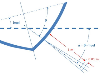
In the project that I am considering, 2 transducers will be able to measure the component of the speed of the water parallel to the axis of the ultrasonic beam at a distance of 30 cm from the hull.

By knowing the installation and the heel angles, it is then possible to calculate the lateral speed of the boat.


A good introduction to the pulse-to-pulse coherent Doppler technique can be found in these documents:


“Pure coherent Doppler systems – how far can we push it?”  Lohrman and Nylund, 2008.


“Performance of a Single-Beam Pulse-to-Pulse Coherent Doppler Profiler”  Zedel, Hay, Cabrera and Lohrmann, 1996.

Wednesday, November 9, 2011

A custom acoustic doppler velocimeter?

This recent Sailing Anarchy entry about acoustic doppler velocimetry really got my attention, and I am thinking about developing a custom prototype.

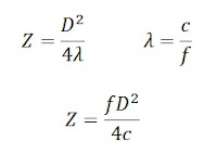
My current understanding is that with this technology, you can measure the flow velocity at a certain distance of the transducer, beyond the near field described in this figure.


The length Z of the near field depends on the diameter D of the emitter, and on the wavelength λ of the signal. The wavelength λ is related to the frequency f of the signal and on the speed of sound c in the water (around 1500 m/s).


For example, a 25 mm emitter operating at 3 MHz would yield a near field of 0.31 m (12 in). This example is not totally arbitrary because, as an element of motivation, I have already ordered a pair of piezoelectric transducers with these exact characteristics from this source.


I will now try to identify what kind of electronics and software will be needed to eventually get a working unit.

Tuesday, November 8, 2011

Damping AWA, TWA and heading values

Damping values is typically achieved by updating a running average of an appropriate number of past measurements.  But calculating averages of AWA, TWA and heading values presents a problem.

AWA and TWA use values between -180 and +180 deg. The problem occurs when the values to average cross the +-180 line.  For example the arithmetic average of -170 and + 160 deg is -5 deg instead of the correct average of +175 deg.

Compass headings use values between 0 and 360 deg. Here the problem arises when the values to average cross the 0 deg line. For example, the arithmetic average of 350 and 20 deg gives 185 deg instead of the correct 5 deg.

The solution developed here is to keep a double accounting of all the angles, one in the -180 to 180 range, the other in the 0 to 360 range. The average is calculated in both ranges, but only one is valid. The right value is identified and converted to original range if necessary.
Here is the algorithm used for averaging  AWA (or TWA) values.

// AWA values to average (-180 to 180)
double awa[5] = {-170.0, -170.0, 175.0, 175.0, 175.0);
// alternate list (0 to 360)
double awa_alt[5];
// build the alternate list (0 to 360)
for(i = 0; i < 5; i++)
{
  if(awa[i] < 0.0)
    awa_alt[i] = awa[i] + 360.0;
  else awa_alt[i] = awa[i];
}
/*
  Alternate list: 190, 190,  175, 175, 175
*/
// calculate the average of both lists
double awa_av = 0.0;
double awa_alt_av = 0.0;
for(i = 0; i < 5; i++)
{
  awa_av += awa[i];
  awa_alt_av += awa_alt[i];
}

awa_av /= 5;
awa_alt_av /= 5;
/*
  awa_av = 37.0, awa_alt_av = 181.0
*/
// find min and max of original list
double minang = 999.0;
double maxang = -999.0;
for(i = 0; i < 5; i++)
{
  if(awa[i] < minang)
    minang = awa[i];
  if(awa[i] > maxang)
    maxang = awa[i];
}
/*
  minang = -170, maxang = 175
*/

double minmax = minang * maxang;
/*
  minmax = -29750
*/
/*
If minmax is positive, this means that the
original values were either all positive or
all negative, and the original average is
valid. If minmax is negative, this means that
the wind crossed the axis of the boat. If a front
wind crossed the axis of the boat, the original
average is valid. If a rear wind crossed the
axis of the boat, then the alternate average
(0 to 360) is valid, and must be converted back
to -180 to 180.
*/

if(minmax < 0.0) // wind crossed axis of the boat
{
  if(minang < -90.0)   // rear wind, take 0-360 average
  {
    // convert to -180 to 180
    if(awa_alt_av > 180.0)
      awa_av = awa_alt_av - 360.0;
    else
      awa_av = awa_alt_av;
  }
}
/*
 At this point, the variable awa_av contains
 the correct average of -179.0 deg.
*/
 
Some practical results using this algorithm can be seen here.


Tuesday, November 1, 2011

Wind vane microcontroller code

Here is the code now used to calculate the measured apparent wind angle in this system.

The analog-to-digital code makes use of the files ‘adc.h’ and ‘adc.c’ found in this BDMICRO sample code. These 2 files shall be included in the project and be part of the compilation.


//...
#include "adc.h"
//...

#define PI 3.14159265
#define DEG_TO_RAD ((double)(PI/180.0))
#define RAD_TO_DEG ((double) (180.0/PI))

double awa_measured;

// Wind vane calibration data
double wcx[2];
double wcy[2];
double xc;
double yc;
uint16_t green, blue;

int main(void)
{
   // ...
  
   xc = 741.2638;
   yc = 744.6921;
   wcx[0] = 1.002073;
   wcx[1] = -0.006924865;
   wcy[0] = -0.006924865;
   wcy[1] = 1.023132;
  
   /* initialize A/D Converter */
   adc_init();
  
   for(;;)
   {
      // begin a new cycle
      // ...
 
      green = adc_readn(0, 10);  /* sample channel #0 10 times, take average */
      blue = adc_readn(1, 10);   /* sample channel #1 10 times, take average */
   
      double dgreen = ((double)green) - xc;
      double dblue = ((double)blue) - yc;
      double xmap = wcx[0] * dgreen + wcx[1] * dblue;
      double ymap = wcy[0] * dgreen + wcy[1] * dblue;
   
      awa_measured = atan2(ymap, xmap) * RAD_TO_DEG;
   
      // ...
    
      // Wait for timer signal to begin a new cycle
      
      // ...
   }
}

Monday, October 31, 2011

New wind vane calibration

In the second post of this blog, I described a rather complicated method to calibrate the Raymarine ST60+ wind vane transducer. I have now identified a simplified and more robust way to do the same.

The following figure illustrates the interface between the Raymarine transducer and the microcontroller.  With the regulated supply voltage now reduced from 8 to 7.25 V, the wind vane produces 2 analog signals (the green and blue wires), varying between 2.4 and 4.8 volts.


The analog signals are fed directly to two ADC (analog-to-digital) pins of the microcontroller. The microcontroller uses a 5 V volt reference to convert the signals to a number ranging from 0 to 1023.

This is the form of the signals produced when the vane is rotated through a complete turn from 0 (wind from the front of the boat) to 360 degrees, clockwise from above.


When the mast was down (instead of climbing up there), I manually rotated the vane and recorded the blue and green ADC signals at several angles around a full turn, first clockwise and then counterclockwise.

Then the green/blue pairs are graphed as X,Y points in Excel.


This may look like a circle, but it is in fact a slightly eccentric ellipse, with its axis tilted, and its center slightly off the main diagonal. The next step is to find the equation of the ellipse that best fits these points. For this step, we use the NLREG software which has a convenient example of fitting an ellipse to data points.

Using the NLREG software, we obtain the following characteristics for the fitted ellipse:

     Parameter        Final estimate
------------------  ------------------ 
           Xcenter           741.363842     
           Ycenter           744.69208
           Tilt Angle (T)    1.86167052 radian
           Xdim               243.159241
           Ydim               249.288046
 
The calibration technique consists in mapping the ellipse to a circle centered at the origin (0,0). For each green/blue measurement pair (x_green, y_blue), the apparent wind angle can then be calculated by the following procedure.


The equation reduces to:


And the measured apparent wind angle can be calculated as:


Friday, October 28, 2011

Hi-Resolution Custom Compass

I have completed the assembly of my custom compass.


As explained in a previous post, it has a resolution of better than 0.1 degree, and calculates a new tilt-compensated heading more than 10 times per second.

To achieve the output rate of 10 Hz, the compass makes use of 3 MicroMag3 magnetometers working in parallel, each one being responsible for only one axis. In the following figure, the active coil of each magnetometer is marked by a red circle.


I came to the conclusion that a gyro is not needed in a marine compass, as the rate of turn can be calculated from the calibrated output of a fast compass.

The final accuracy of a compass depends entirely on the quality of the calibration, that will be completed as described in the last 3 posts.

After that, I will make comparative tests between this compass and the Airmar H2183.


UPDATE: Some test results


Here is a graph comparing the calibrated output of both compass during a short test run (click on the figure to zoom in). The Airmar H2183 is in blue, and the Hi-Res is in red. Each horizontal division is 0.1 second, so that this excerpt covers around 2 minutes. Over the extended test run that had a duration of 6 minutes, the average difference between the 2 compass has been 0.1 degree. The H2183 seems to overreact somewhat to changes in heading and may thus require more damping. This is also evident from the calibration test run (http://sailboatinstruments.blogspot.ca/2012/06/compass-calibration-on-water.html). I did not found the time to test the instantaneous readings during a typical tack as planned, this will be for next summer. Bottom line : quality of calibration is much more imporant that anything else.


Monday, October 17, 2011

New tilt compensation

To calculate a tilt-compensated magnetic heading, we start with x-y-z raw measurements from the accelerometer (arx, ary, arz) and from the magnetometer (mrx, mry, mrz).

First, we need to find the orientation of the magnetometer reference frame (ax, ay, az) in the gravitational field.

This is given by:


The 3 correction matrices and the 3 bias values have been established during the calibration process. The 3 matrices can be pre-multiplied in order to simplify future calculations.  For the example presented in the last 2 posts, the equation reduces to:


We then normalize this result:

We now calculate the calibrated magnetometer values (mx, my, mz):

For the example presented in the last 2 posts, we have:


And finally, the tilt compensated heading is given by:


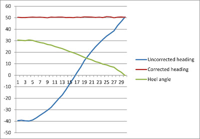
In the following example, the compass base is tilted on its side to produce a heel angle of around 30 degrees, and then slowly comes back to horizontal, as shown by the green curve. This produces a huge variation in the uncorrected heading (the blue curve). The tilt compensation does an excellent job, as the red curve is truly horizontal.


To see the improvement of the calibration, compare with the similar example appearing in this older post

Friday, October 14, 2011

New magnetometer calibration

The magnetometer calibration of the prototype compass uses the same arrangement that was described in the last post for the accelerometer.


In magnetometer calibration mode, when the button is pressed, 16 consecutive MicroMag3 raw measurements are sent to the serial port. A remote laptop running Hyperterminal continually saves these measurements in a text file. The compass assembly is rotated step by step around the X axis and measurements are taken after each small rotation. Then the procedure is repeated around the Y axis.

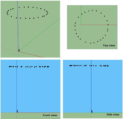
The following figure illustrates the first set of measurements taken with this arrangement, as rendered in Google Sketchup.


The resulting text file is then processed by the Magneto software to find the calibration parameters.


The compass base is then placed completely horizontal, and a set of measurements are made by rotating the compass assembly around the Z axis. The following figure illustrates the measurements taken with this arrangement, as rendered in Google Sketchup.


For each of these raw measured points (mrx, mry, mrz), we calculate their calibrated values (mx, my, mz).


We now want to find the equation of the plane (ax + by + cz + d = 0) that best fits these calibrated points. Using the NLREG software, we find the following equation parameters:


a = 0.0125592224
b = 0.00391778749
c = 1      
d = -3166.69898

The vector normal to the plane (vector v3) is then (a, b, c)
= (0.0125592224, 0.00391778749, 1) with a calculated norm of 1.000087.

This vector represents the orientation of the magnetometer reference frame in the rigid base reference frame.


We can thus conclude that when the orientation of the magnetometer reference frame in the gravitational field is  v3 = (0.0125592224, 0.00391778749, 1), then the orientation of the rigid base in the gravitational field is v2 =  (0.0, 0.0, 1.000087).

From the values of vectors v2 and v3, it is now possible to calculate the rotation matrix that can be applied to any vector v2 (orientation of the rigid base in the gravitational field) to get the associated vector v3 (orientation of the magnetometer reference frame in the gravitational field):


We will also need this rotation matrix later on for the tilt compensation corrections.


Thursday, October 6, 2011

New accelerometer calibration

A first prototype of a custom compass has been built, and an improved calibration procedure for the accelerometer has been tested.


The compass has 4 components mounted on a rigid base:
  • a small board featuring an ATmega128A microprocessor operating at 3.3V and 8 MHz
  • a MicroMag 3-axis magnetometer
  • an SCA3000 3-axis accelerometer
  • an NCP1400-5V Step-Up board acting as a power supply to the SCA3000.
The compass base has been fitted with wooden pegs on the X and Y axis. When supported at each end of the X or Y axis peg, the compass assembly can be rotated a full 360 degrees for calibration purposes.

Four flexible wires connect the compass to a remote 3.3 V power supply, a remote serial-to-USB converter, and a remote momentary-contact button. This configuration corresponds to the intended installation on the boat.

In accelerometer calibration mode, when the button is pressed, 64 consecutive raw measurements are sent to the serial port. A remote laptop running Hyperterminal continually saves these measurements in a text file. The compass assembly is rotated step by step around X axis and measurements are taken after each small rotation. Then the procedure is repeated around Y axis.

The following figure illustrates the first set of measurements taken with this arrangement, as rendered in Google Sketchup.


The resulting text file is then processed by the Magneto software to find the calibration parameters.


The compass base is then placed completely horizontal, and a set of measurements (64 consecutive values) is taken at this position. The average of these 64 raw measurements is:
   arx = -93.7656     ary = 61.56813    arz = 1420.344

After applying the calibration correction,


we obtain:
   aax = -0.2244         aay = 68.61544        aaz = 1332.229      (vector v1)
and the norm for these calibrated values is calculated at 1333.995, which is a comforting result.

These calibrated values describe the orientation of the accelerometer reference frame in the gravitational field.

From the calibrated values, the heel and pitch values are calculated at  -2.95 deg (heel) and 0.010 deg (pitch). These angles reflect the orientation of the accelerometer vs the rigid base.

At this same horizontal position, we conclude that the orientation of the rigid base in the gravitational field is described as:

abx = 0.0       aby = 0.0        abz = 1333.995     (vector v2)

From the values of vectors v1 and v2, it is now possible to calculate the rotation matrix that can be applied to any calibrated vector v1 (accelerometer orientation) to get the associated vector v2 (rigid base orientation) :


The technique to calculate a rotation matrix from 2 vectors is documented here.

We will need this rotation matrix later on for the tilt compensation corrections.

The next step is to apply the same calibration procedure to the magnetometer.


Wednesday, September 7, 2011

Improved magnetometer calibration (Part 2)

In Part 1 of this post, I have presented the MagCal software that is used to calibrate a 3-axis magnetometer (or accelerometer).

One problem with MagCal is that one of the results (the matrix A) cannot be used directly. You have to calculate the inverse matrix A-1.  The other problem is that the matrix A elements have a limited number of significant digits, which affects the precision of the inverted result. And finally, the raw measurements numbers cannot be greater than 99.99, so that you may have to scale down all your data to use it.

I present here my alternate implementation called Magneto, which calculates directly the required matrix A-1.  It also presents the inverted A matrix to permit a comparison with MagCal results.

Magneto v1.2 can be downloaded here:
https://sites.google.com/view/sailboatinstruments1


What are the differences between MagCal and Magneto?
 
Both find the equation of an ellipsoid that best fits the raw data points, using however different techniques. MagCal uses an “adaptive least square estimator”, and Magneto uses the “Li's ellipsoid specific fitting algorithm”. Which one is better? I don’t know, but the authors that have developed MagCal suggest in a recent paper that they may now use Li’s method.

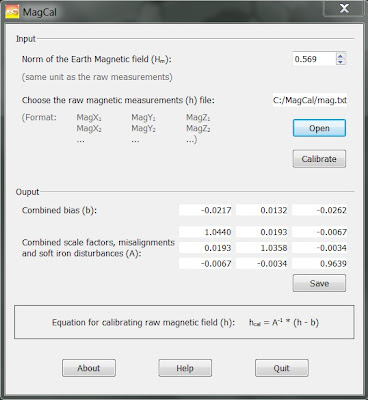
Here is the output of both softwares, using the same raw data file provided with MagCal.


As you can see, the results are nearly identical. I plan to add new features and to fully document Magneto on its hosting site when time permits.

Tuesday, August 30, 2011

Improved magnetometer calibration (Part 1)

Note: the MagCal software is no longer available on the University of Calgary site. See Part 2 of this post for the replacement Magneto software.
______________________________

After looking at a number of recent papers on magnetometer calibration, I have decided on the following path to improve the calibration of a custom compass under development.

It is based on the availability of a PC software tool called MagCal.exe, developed by the PLAN Research Group at the University of Calgary, Alberta, Canada.

First, here is how to get the software:
     1. Go to their website: http://plan.geomatics.ucalgary.ca/
     2. On their menu bar, select Research, then Publications
     3. Type MagCal in the Search Criteria textbox, then click on the ‘Search’ button.
     4. Right click on ‘Download Executable’, then pick ‘Save target as…’ in the pop-up menu
     5. Save the MagCal.zip file on your machine
     6. Unzip, and you are ready to go.


You can also download the PDF paper on which the software is based at the same location.


So what MagCal exactly does? As stated in the about box: “This code computes the calibration parameters of a tri-axis magnetometer”.

From an input file containing raw measurement of the magnetometer, it finds 12 calibration values that correct for a whole set of errors: bias, hard iron, scale factor, soft iron and misalignments.  Note that you will have to invert a 3x3 matrix result (there are online tools for that). What they don’t tell is that the same software can also be used to calibrate the accelerometer for bias, scale factor AND misalignments.

Here is a rendering (using Google SketchUp) of the example raw data file provided with the MagCal software.


The whole idea is to first make this calibration on the completed compass in a magnetic clean environment (like an exterior isolated field).

The whole calibration procedure will be like this:
     1. Record a set of static measurements (magnetometer and accelerometer) by positioning the compass in a large number of orientiations covering a whole sphere
     2. Process the data in MagCal to find the calibration values (12 each for the magnetometer and the accelerometer)
     3. Carefully position the compass assembly completely horizontal (use a precision level).
     4. Record the accelerometer output at this position, to find the orientation of the accelerometer versus the whole compass assembly. This will be used to apply a final correction to the calibrated accelerometer values before applying the tilt compensation equations.

Note that once the compass will be installed in the boat, there may be additional hard and soft iron errors induced by the boat structure and equipment.  These will be later identified with the help of the GPS, as shown in a previous post.

In Part 2 of this post, I present 'Magneto', a similar software tool which has some practical advantages compared to 'MagCal'.

Monday, July 18, 2011

Interfacing the LS20031 GPS Receiver

This system currently gets GPS data from an LS20031 GPS receiver, interfaced to the Olimex I2C client. In order to configure the GPS, it is convenient to use the MiniGPS software available on the SparkFun site for this product.

Here is a configuration arrangement where a CP2102 USB converter is used for communication to the PC running MiniGPS, as well as a 3.3 V power supply to the GPS.


The MiniGPS software has been used to configure the $GPRMC NMEA 0183 sentence at a baud rate of 9600, with an update rate of 5 Hz, and WAAS enabled ( I am currently using an older 5 Hz LS20031 version, soon to be replaced by the 10 Hz one).

Here is the format of the output sentence:
               $GPRMC,180846.600,A,4659.9999,N,07059.9999,W,6.00,45.00,050210,,,D*77
where the 6 numbers to be extracted are highlighted. The latitude and longitude are each read as 2 integer values to avoid rounding errors here, followed by the SOG and COG floating point values.

WARNING: the onboard battery will keep the configuration up to several weeks if the GPS is not powered during this time, and will then revert to the default configuration with a 57600 baud rate. After a winter season on the dry, the configuration step has to be repeated.
 
Once configured, here is how the GPS is interfaced to the microcontroller, using a logic level converter to step up the NMEA output from 3.3 to 5 V. This is a good illustration of the kind of punishment you deserve when you mix 3.3 V sensors with 5 V microprocessors.


Here is the part of the code used by the Olimex microprocessor to parse the NMEA data from the GPS.
unsigned static char buf0[500];
volatile unsigned char temprec0;
volatile unsigned char idx0 = 0;
typedef union
{
   unsigned char messageBuf[36];
   struct
   {
      double heading;   // magnetic heading from gyrocompass
      double heel;   // heel angle from gryrocompass
      double pitch;   // pitch angle from gyrocompass
      double rot;    // rate of turn from gyrocompass
      double cog;    // COG from GPS
      double sog;    // SOG from GPS
      int long1;    // longitude (1st part) from GPS
      int long2;    // longitude (2nd part) from GPS
      int lat1;    // latitude (1st part) from GPS
      int lat2;    // latitude (2nd part) from GPS
      double speed2;    // boat speed from port transducer
   };
} package;

volatile package pack;

/* This interrupt routine is called each time a new character
   is received from the GPS NMEA stream. When the end of
   a NMEA sentence is detected (by the '\n' character), the
   complete sentence accumulated in the 'buf0[]' buffer is deciphered,
   the desired numbers are extracted and put in the 'pack' repository,
   that is used for the I2C transfer to the main controller.
*/
ISR(USART0_RX_vect)
{
   temprec0 = UDR0;
   if(temprec0 != '\n')
   {
      buf0[idx0++] = temprec0;
   }
   else
   {
     buf0[idx0] = '\0';
     idx0 = 0;
     if(buf0[0] == '$')
     {
        // $GPRMC,180846.600,A,4659.9999,N,07059.9999,W,6.00,45.00,050210,,,D*77
        sscanf(&(buf0[20]), "%d", &pack.lat1);
        sscanf(&(buf0[25]), "%d", &pack.lat2);
        sscanf(&(buf0[33]), "%d", &pack.long1);
        sscanf(&(buf0[38]), "%d", &pack.long2);
        sscanf(&(buf0[45]), "%lf,%lf", &pack.sog, &pack.cog);
     }
   }
}
int main(void)
{
   ...
   /* USART0 */
   /* Set baud rate : 9600 @ 16MHz */
   UBRR0L = (unsigned char)(103);
   /* Enable receiver and interrupt on received characters */
   UCSR0B = _BV(RXEN) | _BV(RXCIE);
   idx0 = 0;
 
   ...
}