Wednesday, September 7, 2011

Improved magnetometer calibration (Part 2)

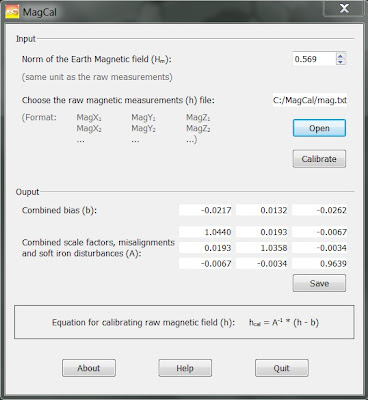
In Part 1 of this post, I have presented the MagCal software that is used to calibrate a 3-axis magnetometer (or accelerometer).

One problem with MagCal is that one of the results (the matrix A) cannot be used directly. You have to calculate the inverse matrix A-1.  The other problem is that the matrix A elements have a limited number of significant digits, which affects the precision of the inverted result. And finally, the raw measurements numbers cannot be greater than 99.99, so that you may have to scale down all your data to use it.

I present here my alternate implementation called Magneto, which calculates directly the required matrix A-1.  It also presents the inverted A matrix to permit a comparison with MagCal results.

Magneto v1.2 can be downloaded here:
https://sites.google.com/view/sailboatinstruments1


What are the differences between MagCal and Magneto?
 
Both find the equation of an ellipsoid that best fits the raw data points, using however different techniques. MagCal uses an “adaptive least square estimator”, and Magneto uses the “Li's ellipsoid specific fitting algorithm”. Which one is better? I don’t know, but the authors that have developed MagCal suggest in a recent paper that they may now use Li’s method.

Here is the output of both softwares, using the same raw data file provided with MagCal.


As you can see, the results are nearly identical. I plan to add new features and to fully document Magneto on its hosting site when time permits.

Tuesday, August 30, 2011

Improved magnetometer calibration (Part 1)

Note: the MagCal software is no longer available on the University of Calgary site. See Part 2 of this post for the replacement Magneto software.
______________________________

After looking at a number of recent papers on magnetometer calibration, I have decided on the following path to improve the calibration of a custom compass under development.

It is based on the availability of a PC software tool called MagCal.exe, developed by the PLAN Research Group at the University of Calgary, Alberta, Canada.

First, here is how to get the software:
     1. Go to their website: http://plan.geomatics.ucalgary.ca/
     2. On their menu bar, select Research, then Publications
     3. Type MagCal in the Search Criteria textbox, then click on the ‘Search’ button.
     4. Right click on ‘Download Executable’, then pick ‘Save target as…’ in the pop-up menu
     5. Save the MagCal.zip file on your machine
     6. Unzip, and you are ready to go.


You can also download the PDF paper on which the software is based at the same location.


So what MagCal exactly does? As stated in the about box: “This code computes the calibration parameters of a tri-axis magnetometer”.

From an input file containing raw measurement of the magnetometer, it finds 12 calibration values that correct for a whole set of errors: bias, hard iron, scale factor, soft iron and misalignments.  Note that you will have to invert a 3x3 matrix result (there are online tools for that). What they don’t tell is that the same software can also be used to calibrate the accelerometer for bias, scale factor AND misalignments.

Here is a rendering (using Google SketchUp) of the example raw data file provided with the MagCal software.


The whole idea is to first make this calibration on the completed compass in a magnetic clean environment (like an exterior isolated field).

The whole calibration procedure will be like this:
     1. Record a set of static measurements (magnetometer and accelerometer) by positioning the compass in a large number of orientiations covering a whole sphere
     2. Process the data in MagCal to find the calibration values (12 each for the magnetometer and the accelerometer)
     3. Carefully position the compass assembly completely horizontal (use a precision level).
     4. Record the accelerometer output at this position, to find the orientation of the accelerometer versus the whole compass assembly. This will be used to apply a final correction to the calibrated accelerometer values before applying the tilt compensation equations.

Note that once the compass will be installed in the boat, there may be additional hard and soft iron errors induced by the boat structure and equipment.  These will be later identified with the help of the GPS, as shown in a previous post.

In Part 2 of this post, I present 'Magneto', a similar software tool which has some practical advantages compared to 'MagCal'.

Monday, July 18, 2011

Interfacing the LS20031 GPS Receiver

This system currently gets GPS data from an LS20031 GPS receiver, interfaced to the Olimex I2C client. In order to configure the GPS, it is convenient to use the MiniGPS software available on the SparkFun site for this product.

Here is a configuration arrangement where a CP2102 USB converter is used for communication to the PC running MiniGPS, as well as a 3.3 V power supply to the GPS.


The MiniGPS software has been used to configure the $GPRMC NMEA 0183 sentence at a baud rate of 9600, with an update rate of 5 Hz, and WAAS enabled ( I am currently using an older 5 Hz LS20031 version, soon to be replaced by the 10 Hz one).

Here is the format of the output sentence:
               $GPRMC,180846.600,A,4659.9999,N,07059.9999,W,6.00,45.00,050210,,,D*77
where the 6 numbers to be extracted are highlighted. The latitude and longitude are each read as 2 integer values to avoid rounding errors here, followed by the SOG and COG floating point values.

WARNING: the onboard battery will keep the configuration up to several weeks if the GPS is not powered during this time, and will then revert to the default configuration with a 57600 baud rate. After a winter season on the dry, the configuration step has to be repeated.
 
Once configured, here is how the GPS is interfaced to the microcontroller, using a logic level converter to step up the NMEA output from 3.3 to 5 V. This is a good illustration of the kind of punishment you deserve when you mix 3.3 V sensors with 5 V microprocessors.


Here is the part of the code used by the Olimex microprocessor to parse the NMEA data from the GPS.
unsigned static char buf0[500];
volatile unsigned char temprec0;
volatile unsigned char idx0 = 0;
typedef union
{
   unsigned char messageBuf[36];
   struct
   {
      double heading;   // magnetic heading from gyrocompass
      double heel;   // heel angle from gryrocompass
      double pitch;   // pitch angle from gyrocompass
      double rot;    // rate of turn from gyrocompass
      double cog;    // COG from GPS
      double sog;    // SOG from GPS
      int long1;    // longitude (1st part) from GPS
      int long2;    // longitude (2nd part) from GPS
      int lat1;    // latitude (1st part) from GPS
      int lat2;    // latitude (2nd part) from GPS
      double speed2;    // boat speed from port transducer
   };
} package;

volatile package pack;

/* This interrupt routine is called each time a new character
   is received from the GPS NMEA stream. When the end of
   a NMEA sentence is detected (by the '\n' character), the
   complete sentence accumulated in the 'buf0[]' buffer is deciphered,
   the desired numbers are extracted and put in the 'pack' repository,
   that is used for the I2C transfer to the main controller.
*/
ISR(USART0_RX_vect)
{
   temprec0 = UDR0;
   if(temprec0 != '\n')
   {
      buf0[idx0++] = temprec0;
   }
   else
   {
     buf0[idx0] = '\0';
     idx0 = 0;
     if(buf0[0] == '$')
     {
        // $GPRMC,180846.600,A,4659.9999,N,07059.9999,W,6.00,45.00,050210,,,D*77
        sscanf(&(buf0[20]), "%d", &pack.lat1);
        sscanf(&(buf0[25]), "%d", &pack.lat2);
        sscanf(&(buf0[33]), "%d", &pack.long1);
        sscanf(&(buf0[38]), "%d", &pack.long2);
        sscanf(&(buf0[45]), "%lf,%lf", &pack.sog, &pack.cog);
     }
   }
}
int main(void)
{
   ...
   /* USART0 */
   /* Set baud rate : 9600 @ 16MHz */
   UBRR0L = (unsigned char)(103);
   /* Enable receiver and interrupt on received characters */
   UCSR0B = _BV(RXEN) | _BV(RXCIE);
   idx0 = 0;
 
   ...
}

Saturday, July 16, 2011

I2C Transfer between 2 microcontrollers

In this system, the Olimex board is programmed as an I2C client, and the main controller as an I2C master.


  I2C Client Side

The I2C client code is based on Atmel Application Note AVR311: “Using the TWI module as I2C slave”, and the corresponding Atmel files ‘TWI_Slave.h’ and ‘TWI_Slave.c’. These 2 files shall be included in the project and be part of the compilation. The following line of the ‘TWI_Slave.h’ file should however be changed from:
               #define TWI_BUFFER_SIZE 4
to:
                #define TWI_BUFFER_SIZE 36

Here, we chose a very minimalist implementation where the I2C client is always addressed for reading by the master, never for writing. Each time the I2C client is addressed for reading, it expects that the master will always request a fixed number of 36 bytes.

With this minimal implementation, the required I2C client code is deceptively simple. It requires only the following lines, where ‘ens.messageBuf’ is the address of the first byte of the 36-byte buffer to transmit. The buffer is continually updated by the interrupt service routines of the GPS, the gyrocompass and one of the speed transducers.


#include "TWI_Slave.h"


int main(void)
{
   unsigned char TWI_slaveAddress;

  
   // Own TWI slave address
   TWI_slaveAddress = 0x10;


   // Initialise TWI module for slave operation.
   // Include address and/or enable General Call.
   TWI_Slave_Initialise( (unsigned char)((TWI_slaveAddress<<TWI_ADR_BITS)
      | (TRUE<<TWI_GEN_BIT) ));

  
   …
   // Start the TWI transceiver to enable reseption of the first command

   // from the TWI Master.
   TWI_Start_Transceiver_With_Data((char*)(ens.messageBuf), 36);

   for(;;)
   {
      if (!TWI_Transceiver_Busy())
      {
         TWI_Start_Transceiver_With_Data((char*)(ens.messageBuf), 36);
      }
   }
}


I2C Master Side

Here the code used by the Mavric-IIB master controller to read the I2C client buffer.

typedef union  //  this is the same data structure used by the client
{
   unsigned char messageBuf[36];
   struct
   {
      double heading;
      double heel;
      double pitch;
      double rot;
      double cog;
      double sog;
      int long1;
      int long2;
      int lat1;
      int lat2;
      double speed2;
   };
} package;

volatile package pack;
...

int main(void)
{
   ...
   /* set the I2C bit rate generator to 100 kb/s */
   TWSR &= ~0x03;
   TWBR  = 28;
   TWCR |= _BV(TWEN);

   ...

   for(;;)  
   {
      // begin a new cycle
      ...
  
      // fetch the I2C client

     
      // I2C start
      TWCR = (_BV(TWINT) | _BV(TWEN) | _BV(TWSTA));
      while(!(TWCR & _BV(TWINT)));
     

      // select Olimex client (I2C address 0x10) for reading
      TWDR = (0x10 << 1) + 1;
      TWCR = (_BV(TWINT) | _BV(TWEN));
     
while(!(TWCR & _BV(TWINT)));
     

      // read the first 35 bytes, with acknowledge request
      for(i = 0; i < 35; i++)
      {
         TWCR = _BV(TWINT) | _BV(TWEN) | _BV(TWEA);
         while(!(TWCR & _BV(TWINT)));
         pack.messageBuf[i] = (unsigned char)TWDR;
      }
     

      // read the last byte without acknowledge request
      TWCR = _BV(TWINT) | _BV(TWEN);
      while(!(TWCR & _BV(TWINT)));
      pack.messageBuf[35] = (unsigned char)TWDR;
     

      // I2C stop
      TWCR = _BV(TWINT) | _BV(TWEN)| _BV(TWSTO);
      while(TWCR & _BV(TWSTO));
  
      ...
      // wait for a timer signal to begin a new cycle
      ...

   }
}


WARNING : this is a minimalist implementation of I2C for the ATMega128, without any error checking. If the I2C link between the master and the client is disconnected, the master will hang forever. This would not be acceptable in a commercial or distributable product, but the objective here was to keep the code as simple as possible.

Sunday, July 10, 2011

Interfacing the Airmar H2183 Gyrocompass (Part 2)

Here is the part of the code used by the Olimex microcontroller to parse the gyrocompass NMEA data. The I2C transfer code (using Atmel "TWI_Slave.h") will be further documented in a future post.

#include <stdio.h>
#include <avr/io.h>
#include <avr/interrupt.h>
#include "TWI_Slave.h"
#include <string.h>
#include <stdlib.h>
#include <uart.h>
#include <math.h>


unsigned static char buf[500];
volatile unsigned char temprec;
volatile unsigned char idx = 0;
double theta_rad, dtheta_rad, deviation;


...

typedef union
{
  unsigned char messageBuf[36];

  struct
  {
    double heading;   // magnetic heading from gyrocompass
    double heel;   // heel angle from gryrocompass
    double pitch;   // pitch angle from gyrocompass
    double rot;    // rate of turn from gyrocompass
    double cog;    // COG from GPS
    double sog;    // SOG from GPS
    int long1;    // longitude (1st part) from GPS
    int long2;    // longitude (2nd part) from GPS
    int lat1;    // latitude (1st part) from GPS
    int lat2;    // latitude (2nd part) from GPS
    double speed2;    // boat speed from port transducer

  };
} package;


volatile package pack;

/* This interrupt routine is called each time a new character
   is received from the gyrocompass NMEA stream. When the end of
   a NMEA sentence is detected (by the '\n' character), the
   complete sentence accumulated in the 'buf[]' buffer is deciphered,
   the desired numbers are extracted and put in the 'pack' repository,
   that is used for the I2C transfer to the main controller.
*/

ISR(USART1_RX_vect)
{
  temprec = UDR1;
  if(temprec != '\n')
  {
    buf[idx++] = temprec;
  }
  else
  {
    buf[idx] = '\0';
    idx = 0;
    if(buf[0] == '$')
    {
      if(buf[1] == 'H')
      {
        sscanf(buf, "$HCHDG,%lf", &pack.heading);
 
        // calculate deviation

        theta_rad = pack.heading * 3.14159 / 180.0;
        dtheta_rad = theta_rad * 2.0;
        deviation = 4.103844 - 8.302381 * sin(theta_rad)
           + 15.92628 * cos(theta_rad)
           + 1.519511 * sin(dtheta_rad)
           + 2.346229 * cos(dtheta_rad);
 
        pack.heading -= deviation;
 
        if(pack.heading > 360.0)
          pack.heading -= 360.0;
        else if(pack.heading < 0.0)
          pack.heading += 360.0;
 
      }
      else if(buf[1] == 'P')
        sscanf(buf, "$PFEC,GPatt,,%lf,%lf", &pack.pitch, &pack.heel);
      else if(buf[1] == 'T')
        sscanf(buf, "$TIROT,%lf", &pack.rot);
    }
  }
}


int main(void)
{
  unsigned char TWI_slaveAddress;

  ...
 
  /* USART1 */
  /* Set baud rate : 4800 @ 16MHz */
  UBRR1L = (unsigned char)(207);
  /* Enable receiver and interrupt on received characters */
  UCSR1B = _BV(RXEN) | _BV(RXCIE);
  idx = 0;
 
  ...
 
  // Own TWI slave address
  TWI_slaveAddress = 0x10;

  // Initialise TWI module for slave operation.
  // Include address and/or enable General Call.
  TWI_Slave_Initialise((unsigned char)((TWI_slaveAddress << TWI_ADR_BITS)
                                         |(TRUE<<TWI_GEN_BIT)));  


  sei();
 
  ...
 
  /* Start the TWI(I2C) transceiver to enable reception of the first
     command from the TWI(I2C) Master. This will be further documented
     in a future post on I2C transfer.
  */
  TWI_Start_Transceiver_With_Data((char*)(pack.messageBuf), 36);
  
  for(;;)
  {
    if (!TWI_Transceiver_Busy())
      TWI_Start_Transceiver_With_Data((char*)(pack.messageBuf), 36);
  }
}

Interfacing the Airmar H2183 Gyrocompass (Part 1)

In this system, the Olimex microcontroller is used to read the NMEA output from the gyrocompass and from the GPS. It is also programmed as an I2C client that the main controller interrogates ten times per second.

The system actually uses an Airmar H2183 gyrocompass to get heading, heel and pitch angles, and rate of turn values. This compass can provide both NMEA 0183 and NMEA 2000 outputs. Here we use the NMEA 0183 output which is a standard RS232 serial bus.

In order to configure and calibrate the compass, it is necessary to get a specific Airmar cable and USB converter in the following temporary arrangement.


The Airmar WeatherCaster software has been used to configure the following NMEA 0183 sentences:
               $HCHDG (at 5 Hz) for the magnetic heading
               $PFEC,GPatt (at 5 Hz) for the heel and pitch angles
               $TIROT (at 2 Hz) for the rate of turn.

For this selection of outputs, we are limited to 5 Hz by the 4800 baud NMEA 0183 bandwidth.

Here is the format of the output sentences:
               $HCHDG,55.6,0.0,E,,*1F     (magnetic heading : 55.6 deg)
               $PFEC,GPatt,,-8.7,+4.8*63   (pitch angle : -8.7 deg,  heel angle: 4.8 deg)¸
               $TIROT,4.3,A*3C   (rate of turn:  4.3 deg/min).

The WeatherCaster software has also an autocalibration routine, but it is almost necessary to use a custom calibration, as explained in a previous post: http://sailboatinstruments.blogspot.com/2011/01/gyro-compass-calibration.html

Once configured, here is how the compass is interfaced to the microcontroller, using a Conxall CX-428-8-pin connector :
http://www.blueheronmarine.com/Conxall-CX-428-8-Pin-Panel-Mount-Socket-Male-6907


Here is the pin-out of the WS-C01 cable. On the microcontroller side of the cable, we need to provide +12 V to pin 2, ground pins 1 and 8, and connect pin 5 (A/+ OUT) to the receive pin of the DB9 connector of the Olimex board.

 
In part 2, I will post the microcontroller code used to parse the NMEA sentences.

Thursday, May 26, 2011

True wind, VMG and current calculations


Ten times per second (10 Hz rate), the master controller goes through all true wind, VMG and current calculations. Here the code used for these calculations.

/*
 [this_blog] == sailboatinstruments.blogspot.com
*/


#define PI 3.14159265
#define DEG_TO_RAD ((double)(PI/180.0))
#define RAD_TO_DEG ((double) (180.0/PI))


// Inputs

/* The measured apparent wind angle is the
   calibrated wind vane reading:
   [this_blog]/2011/10/new-wind-vane-calibration.html
*/

double awa_measured;  // -180 to 180 degrees

/* The offset is positive is the masthead unit misalignment is
   clockwise from above, and negative if the misalignment is
   counterclockwise from above. Obtained from calibration test run:
   [this_blog]/2011/02/corrections-to-apparent-wind-angle.html
*/

double offset;  // degrees, positive or negative

/* The measured boat speed is the speed sensor reading,
 [this_blog]/2011/03/measuring-boat-speed-part-1.html
 corrected by a calibration factor from a trial run:
 [this_blog]/2011/01/boat-and-wind-speed-calibration.html
*/

double meas_boat_speed;  // knots


/* The apparent wind speed is the speed sensor reading,
 corrected by a calibration factor from a trial run:
 [this_blog]/2011/01/boat-and-wind-speed-calibration.html
*/

double aws;

/* Heel is positive when the mast leans to starboard,
   and negative when the mast leans to port. Obtained
   from gyro compass.
*/

double heel;   // degrees, positive or negative

/* The leeway calibration factor K is obtained
   from a trial calibration run:
   [this_blog]/2011/02/leeway-calibration.html
*/

double K;

/* The magnetic heading is obtained from the
   gyrocompass reading, corrected for deviation:
   [this_blog]/2011/01/gyro-compass-calibration.html
*/

double heading;  // 0 to 360 deg (magnetic)

/* The COG (course over ground) is the true
   heading from the GPS
*/

double cog;  // 0 to 360 deg (true)

/* The SOG (speed over ground) is the boat speed
   measured by the GPS
*/

double sog;  // knots

/*  Magnetic variation: difference between true and magnetic North
*/

double variation;

// Outputs

double awa_offset;  // AWA corrected for offset (-180 to 180)
double awa_heel;  //   AWA corrected for heel (-180 to 180)

double leeway;    // leeway angle (degrees, positive or negative)
double stw;  // speed through water (knots)
double vmg;  // velocity made good (knots)

double tws;  // true wind speed (knots)
double twa;  // true wind angle (-180 to 180)
double wdir; // wind direction (0 to 360 deg, magnetic)
double soc;  // speed of current (knots)
double doc;  // direction of current (0 to 360 deg, magnetic)


// Correct awa for alignment offset
awa_offset = awa_measured + offset;
if(awa_offset > 180.0)
   awa_offset -= 360.0;
else if(awa_offset < -180.0)
   awa_offset += 360.0;


// Correct awa for heel
double tan_awa = tan(awa_offset * DEG_TO_RAD);
if(isnan(tan_awa))
   awa_heel = awa_offset;
else
{
   double cos_heel = cos(heel * DEG_TO_RAD);
   awa_heel = atan(tan_awa / cos_heel) * RAD_TO_DEG;
 

   if(awa_offset >= 0.0)
   {
      if(awa_offset > 90.0)
         awa_heel += 180.0;
    }
    else
    {
       if(awa_offset < -90.0)
          awa_heel -= 180.0;
    }
}


// Calculate leeway angle
if(meas_boat_speed == 0.0
 || (awa_heel > 0.0 && heel > 0.0)
 || (awa_heel < 0.0 && heel < 0.0))
        leeway = 0.0;
else
{
   leeway = K * heel / (meas_boat_speed * meas_boat_speed);
   // limit leeway value for very low speeds
   if(leeway > 45.0)
      leeway = 45.0;
   else if(leeway < -45.0)
      leeway = -45.0;
}


// Calculate STW (speed through water)
stw = meas_boat_speed / cos(leeway * DEG_TO_RAD);


// Calculate component of stw perpendicular to boat axis
double lateral_speed = stw * sin(leeway * DEG_TO_RAD);

// Calculate TWS (true wind speed)
double cartesian_awa = (270.0 - awa_heel) * DEG_TO_RAD;
double aws_x = aws * cos(cartesian_awa);
double aws_y = aws * sin(cartesian_awa);
double tws_x = aws_x + lateral_speed;
double tws_y = aws_y + meas_boat_speed;
tws = sqrt(tws_x * tws_x + tws_y * tws_y);


// Calculat TWA (true wind angle)
double twa_cartesian = atan2(tws_y, tws_x);
if(isnan(twa_cartesian)) // singularity
{
   if(tws_y < 0.0)
      twa = 180.0;
    else twa = 0.0;
}
else
{
   twa = 270.0 - twa_cartesian * RAD_TO_DEG;
   if(awa_heel >= 0.0)
      twa = fmod(twa, 360.0);
   else
      twa -= 360.0;

   if(twa > 180.0)
      twa -= 360.0;
   else if(twa < -180.0)
      twa += 360.0;
}


// Calculate VMG (velocity made good)
vmg = stw * cos((-twa + leeway) * DEG_TO_RAD);


// Calculate WDIR (wind direction)
wdir = heading + twa;
if(wdir > 360.0)
   wdir -= 360.0;
else if(wdir < 0.0)
   wdir += 360.0;

// Calculate SOC (speed of current)
double cog_mag = cog + variation;
double alpha = (90.0 - (heading + leeway)) * DEG_TO_RAD;
double gamma = (90.0 - cog_mag) * DEG_TO_RAD;
double curr_x = sog * cos(gamma) - stw * cos(alpha);
double curr_y = sog * sin(gamma) - stw * sin(alpha);
soc = sqrt(curr_x * curr_x + curr_y * curr_y);

// Calculate DOC (direction of current)
double doc_cartesian = atan2(curr_y, curr_x);
if(isnan(doc_cartesian))
{
   if(curr_y < 0.0)
      doc = 180.0;
    else doc = 0.0;
}
else
{
   doc = 90.0 - doc_cartesian * RAD_TO_DEG;
   if(doc > 360.0)
      doc -= 360.0;
   else if(doc < 0.0)
     doc += 360.0;
}