Friday, August 22, 2014

A low-cost marine compass (Part 3 – Calibration)

When connected to a terminal program through the FTDI breakout at 115200 baud, the compass displays the results formatted as NMEA sentences. This is the default operating mode (Mode 4 in the software).

Two calibration helper modes are available:
        Mode 1 : Accelerometer  calibration (type M1<ENTER>)
        Mode 2 : Magnetometer calibration (type M2<ENTER>)

These calibration modes are used to produce the raw data files required by the calibration software Magneto. In these modes, the compass stops displaying results until it receives an ‘x’ character (type x<ENTER> in the terminal program).

In Mode 1 (Accelerometer), it will then displays 64 consecutive (x,y,z) filtered raw data (at the 200 Hz rate), then pauses until it receives another ‘x’ character.


In Mode 2 (Magnetometer), it will displays 16 consecutive (x,y,z) raw data (at the 6.5 Hz rate), then pauses until it receives another ‘x’ character.


By logging the results to a text file in the terminal program, it is then possible to create the Magneto input files, by moving the compass around and pressing the ‘x’ character at each new position.

I recommend moving the compass with roughly equal angle steps around three perpendicular axis. For the accelerometer, you can use any support (metallic or not) to help position the compass, but it is very important to wait until the compass is completely at rest (no vibration) before hitting the ‘x’ character.

For the magnetometer, try to use the lightest non-magnetic support (wood or plastic), and use the ribbon cable to keep away the FTDI brekout and especially the laptop (all this in a magnetic clean environment!).

The 2 raw data files can then be processed by the Magneto software. The Pro Mini source file can then be edited with the new values and recompiled.

Unfortunately, this is not the end of the game if we want to be rigorous. We will have to look for misalignments between three independent reference frames: the compass base, the accelerometer plan and the magnetometer plan, with a final offset correction when compared to a known heading.

But the compass should already be quite usable, as these last corrections will be quite small compared to what has been accomplished.


A low-cost marine compass (Part 1 - Hardware)
A low-cost marine compass (Part 2 - Software)


Wednesday, August 20, 2014

A low-cost marine compass (Part 2 – Software)

The problem with low-cost sensors is that the accelerometer outputs are very noisy (much less so for the magnetometer).

The LSM303D sensor is one of 2 magnetic sensors supported by the PX4 development team. The solution they have chosen to reduce the noise in the accelerometer outputs is to apply a low-pass software filter to the measurements, in addition to the hardware low-pass filter built into the chip. In this project, I have ported their LSM303D SPI driver and 2-pole software filter to the WinAVR environment.

I have also kept the strategy adopted for my Hi-Res compass, which is to use a higher sampling rate for the accelerometer, and take the average result in the calculation performed after each magnetometer measurement.

I have chosen a 6.25 Hz sampling rate for the LSM303D magnetometer, to insure that it will operate in its hi-resolution mode. The accelerometer sampling rate is set at 200 Hz, and the cut-off frequency of the software low-pass filter is set at 40 Hz.

Here is a general explanation of the code behaviour during normal operation.

The Pro Mini continually reads triple raw values (x,y,z) from the accelerometer. For each axis, it feeds the raw value to the software low-pass filter, which spits out a new filtered value for each axis. The filtered values are accumulated and counted.

Each time the LSM303D magnetometer has a new set of 3 raw values available (x,y,z), it fires an interrupt on the Pro Mini. When this happens, the Pro Mini applies the calibration correction to the magnetometer values. It calculates the average of the accelerometer filtered values since the last interrupt, and applies the calibration correction. From this set of 6 values, it calculates the tilt-compensated heading, and the heel and pitch angles. It formats the results in 2 NMEA sentences that are sent to the serial port (115200 baud), 6.25 times per second. 


The source code for the WinAVR environment can be found here. I am using Programmer’s Notepad to compile the code and program the Pro Mini through the Arduino bootloader. 

This implies that the calibration factors have already been found since they appear as constants in the code. The software has other modes of operation useful for developing these calibration factors, which will be presented in Part 3 of this series.


A low-cost marine compass (Part 1 – Hardware
A low-cost marine compass (Part 3 - Calibration

Tuesday, August 19, 2014

A low-cost marine compass (Part 1 – Hardware)

For an electronic compass, the accuracy depends more on the quality of the calibration that on the price of the components. Here is the design of a low-cost compass developed around this idea.

The compass is based on the LSM303D chip which combines a 3-axis accelerometer and a 3-axis magnetometer. I used the Pololu carrier board featuring this chip (9.95 US$).


The other component of the compass is an Arduino Pro Mini 328 – 3.3V/8Mhz from Sparkfun (9.95 US$). The Pro Mini communicates with the LSM303D through the SPI bus, using drivers adapted from the PX4 Development Team. The 2 components are hardwired together to keep a compact form.


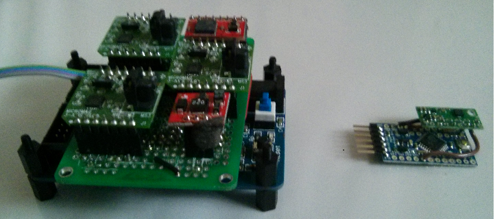
The following picture illustrates the small compass besides my Hi-Resolution custom compass previously described on this blog.


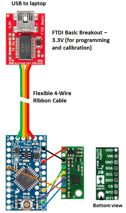
Here is the wiring diagram for SPI communication. The FTDI breakout is used to program the Pro Mini and to read the LSM303D raw data during the calibration step.


The long ribbon cable is required during calibration so that the compass can be moved around at a safe distance from the breakout and the laptop to avoid magnetic interference. After calibration, the ribbon cable is used to power the compass (3.3V) and to transmit the tilt-compensated heading and the heel angle through the serial link to whatever instrument that needs it.


A low-cost marine compass (Part 2 – Software) 
A low-cost marine compass (Part 3 - Calibration)


Wednesday, April 9, 2014

Catamaran’s Sailing Instruments

A catamaran’s owner has decided to adapt my design to his boat, which is sailed on a large freshwater lake. As the lake’s currents are virtually negligible, the boat speed is measured from a GPS. Furthermore, for a catamaran, there is no need to correct wind angle measurements for heel. No electronic compass is planned for now. A Nexus tablet is used as display, with a Bluetooth link to the system.

For a catamaran, as there is no heel, there is no way to calculate the leeway as we do for a keelboat  using boat speed and heel (as described here). So the owner will have to make test runs and physically measure the leeway in different conditions, while logging boat speed, wind speed and apparent wind angle. It is expected that the leeway angle can be correlated to these 3 variables, and that correction curves can be developed and programmed in the microcontroller. For now, the leeway corrections will be neglected until test data are available.


The microprocessor acquires or calculates the following data 10 times per second (10 Hz):
·        Apparent wind angle (AWA)
·        Apparent wind speed (AWS)
·        Boat speed through water (STW = GPS’s SOG)
·        True wind speed (TWS)
·        True wind angle (TWA)
·        Velocity Made Good (VMG)
·        Leeway angle
·        Heading ( = GPS's COG, when not corrected for leeway)
·        Wind direction


These data are available through a serial link, going both to a Bluetooth modem and to serial-to-USB converter.

The Nexus tablet calculates running averages over an adjustable range and refreshes a custom display 10 times per second.

A laptop can be connected to the system to view or change calibration values, or to download live data for further analysis.

The system is now under construction and will soon be installed. Software (both for the microprocessor and the Android tablet) is also under development. The microprocessor code under development (in the WinAVR environment) can be found here. More detailed documentation will be added at the same location.


Tuesday, January 21, 2014

Going Bluetooth with an Android Tablet

After experimenting with Wi-Fi, I have now added a Bluetooth link between my system and an Android tablet. This has proved to be very reliable, and simpler to implement when compared to Wi-Fi.


As the Bluetooth modem operates from a 5 V supply, no level shifting is required on the data line.

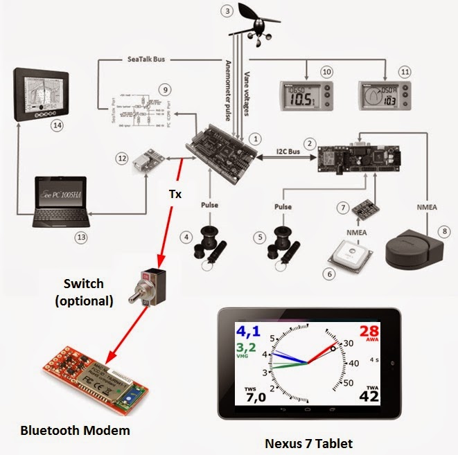
However, there is one constraint that has to be considered. When the tablet tries to connect to the system, the connection will fail if there is data already flowing on the serial output.

There are 2 ways to deal with this:
               - add a switch to manually cut the serial input during the connection step;
               - connect during an initial delay at the system start-up (this is how I proceed, as there is a 10 seconds delay without transmission when my system is switched on).

In my Bluetooth app, the first screen shows a ‘Connect’ button and a disabled ‘Start’ button. The 'Connect' button is pressed when there is no data coming in. Once the connection is established, the ‘Start’ button is enabled and can be pressed to initiate a new thread that decodes the modem output, and pass the information to the main instrument view that is now switched on, refreshed 10 times per second.

The Bluetooth thread also saves all data in a large memory buffer (16 MB) that can store up to 4.5 hours of data per session. When the app is closing, these data are written to a file on the tablet’s internal memory card, that can later be transferred to a PC for analysis.