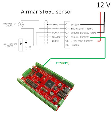
The boat speed is measured with Airmar ST650 speed sensors (similar to the newer ST850). The sensor produces two pulses per revolution of the paddlewheel. The following figure illustrates the interface between the speed sensor and the microcontroller. The ouput signal is fed directly to an input pin of the microcontroller, without further conditioning. The pulses are detected as clean changes in logic level by the internal circuitry of the microcontroller. The thermistor is not used here.
The nominal pulse rate of the ST650 (without fins) is 4.7 Hz per knot. Here is the form of the signal produced for a nominal speed of 3.0 knots.
Conversely, by measuring the time between the rising edges of two pulses, we can calculate the corresponding boat speed:
Speed (knots) = 1 / (delta_t * 4.7)
To measure the time interval, we set up a 16-bit timer running at 16 MHz / 1024 = 15625 Hz. This timer has a resolution of 1/15625 = 0.000064 second. The timer counts from 0 to 65535 then overflows to 0 and up again to 65535. Its time span is thus 65536 * 0.000064 = 4.19 seconds, which corresponds to a nominal boat speed of 1 / (4.19 * 4.7) = 0.05 knot. If the time span between 2 pulses is longer than that, we put the speed to zero. As an example, when the speed is 3.0 knots, there are 0.0709 / 0.000064 = 1108 timer ticks between each pulse. To get the boat speed, we count the timer ticks between each pulse and multiply them by 0.000064 s to get the time interval. We can then calculate the nominal boat speed, which will be multiplied later on by a calibration factor to get the final MBS (measured boat speed).
To implement this in the ATMega128, we use the input capture facility that comes with the internal 16-bit timers. When the rising edge of a new pulse is detected, the current timer value is saved in a special register, and an interrupt is fired. During the interrupt service routine, we calculate the timer counts since the last pulse and put the result in a variable that will be used by the main program to calculate the final boat speed of the current cycle. In the same interrupt routine, we also calculate what will be the timer value 4.19 seconds later. This is a timeout value that we push forward at each new pulse, and should not be attained as long as the boat speed is greater than 0.05 knot.
We set up a second interrupt that fires if the timeout value is attained. In the corresponding interrupt service routine, we set a flag to indicate to the main program that the speed is zero, and that the next pulse will be the first of new series.
All these commentaries will be helpful to follow the code snippets that I will present in Part 2 of this post.


No comments:
Post a Comment