Saturday, November 19, 2011

Doppler profiler: design considerations

With a pulse-to-pulse coherent Doppler profiler, we can pick a specific remote region where we want the measurement to be made. Here we plan to measure the average speed of water in a sample volume of 1 cm long situated at 1 meter from the transducer.


With a speed of sound through water of 1500 m/s, the time to a first echo from the beginning of the sample volume is 1333.3 μs. The time to a first echo from the end of the sample is 1346.7 μs.

To make a measurement, the 3 MHz transducer will send 2 pulses.

After sending the first pulse, the transducer will switch to receive mode and will sample the echo from exactly 1333.3 to 1346.7 μs after the beginning of the pulse. The microprocessor will digitize this echo with its internal 84 MHz ADC and store it in memory. Soon after, the transducer sends a 2nd pulse and the process is repeated.  The second echo is also digitized and stored. As the particles in the water have moved between the 2 samples, the echoes will be separated by a phase angle ϕ (the Doppler shift).  From the stored data, the microprocessor will then calculate the Doppler shift (90 deg in the following figure).


The Doppler shift is related to the component of the speed of the water in the axis of the ultrasonic beam. But there is a problem: more than one velocity value will produce the same Doppler shift.


To pick the right one, we need an external information. In our case, we will calculate an estimate of the lateral speed from the boat's K constant and the current values of boat speed and heel angle. We will then pick the profiler's measurement that is the closest to this estimate.

Saturday, November 12, 2011

A custom coherent Doppler profiler

Here is a preliminary diagram of the prototype profiler that I plan to build.


I intend to modify an existing depth transducer, replacing the piezo disc by a 3 MHz one. This may be the trickiest part.

The frequency generator can be programmed to send either a constant frequency pulse or a variable frequency ('chirp') one. This may be useful later on.

The STM32F4 board will control the frequency generator, and will receive and analyze the echo signals. The STM32F4 microprocessor has built-in DSP (digital signal processing) capabilities.

The total hardware cost (with 2 transducers) should be less than 500 US$. Not too bad for near-America Cup performance, as this could develop in an open software project.

Friday, November 11, 2011

Measuring lateral speed (leeway)

It is possible to measure directly the lateral speed through water of a sailboat making leeway, by using a pulse-to-pulse coherent Doppler profiler. This is the technique used by the Volvo Ocean Race Puma team. In their case, the transducers are installed under the bulb keel.

For a conventional sailboat, a different arrangement can be used.


In the project that I am considering, 2 transducers will be able to measure the component of the speed of the water parallel to the axis of the ultrasonic beam at a distance of 30 cm from the hull.

By knowing the installation and the heel angles, it is then possible to calculate the lateral speed of the boat.


A good introduction to the pulse-to-pulse coherent Doppler technique can be found in these documents:


“Pure coherent Doppler systems – how far can we push it?”  Lohrman and Nylund, 2008.


“Performance of a Single-Beam Pulse-to-Pulse Coherent Doppler Profiler”  Zedel, Hay, Cabrera and Lohrmann, 1996.

Wednesday, November 9, 2011

A custom acoustic doppler velocimeter?

This recent Sailing Anarchy entry about acoustic doppler velocimetry really got my attention, and I am thinking about developing a custom prototype.

My current understanding is that with this technology, you can measure the flow velocity at a certain distance of the transducer, beyond the near field described in this figure.


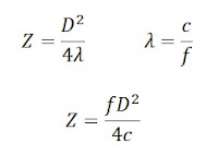
The length Z of the near field depends on the diameter D of the emitter, and on the wavelength λ of the signal. The wavelength λ is related to the frequency f of the signal and on the speed of sound c in the water (around 1500 m/s).


For example, a 25 mm emitter operating at 3 MHz would yield a near field of 0.31 m (12 in). This example is not totally arbitrary because, as an element of motivation, I have already ordered a pair of piezoelectric transducers with these exact characteristics from this source.


I will now try to identify what kind of electronics and software will be needed to eventually get a working unit.

Tuesday, November 8, 2011

Damping AWA, TWA and heading values

Damping values is typically achieved by updating a running average of an appropriate number of past measurements.  But calculating averages of AWA, TWA and heading values presents a problem.

AWA and TWA use values between -180 and +180 deg. The problem occurs when the values to average cross the +-180 line.  For example the arithmetic average of -170 and + 160 deg is -5 deg instead of the correct average of +175 deg.

Compass headings use values between 0 and 360 deg. Here the problem arises when the values to average cross the 0 deg line. For example, the arithmetic average of 350 and 20 deg gives 185 deg instead of the correct 5 deg.

The solution developed here is to keep a double accounting of all the angles, one in the -180 to 180 range, the other in the 0 to 360 range. The average is calculated in both ranges, but only one is valid. The right value is identified and converted to original range if necessary.
Here is the algorithm used for averaging  AWA (or TWA) values.

// AWA values to average (-180 to 180)
double awa[5] = {-170.0, -170.0, 175.0, 175.0, 175.0);
// alternate list (0 to 360)
double awa_alt[5];
// build the alternate list (0 to 360)
for(i = 0; i < 5; i++)
{
  if(awa[i] < 0.0)
    awa_alt[i] = awa[i] + 360.0;
  else awa_alt[i] = awa[i];
}
/*
  Alternate list: 190, 190,  175, 175, 175
*/
// calculate the average of both lists
double awa_av = 0.0;
double awa_alt_av = 0.0;
for(i = 0; i < 5; i++)
{
  awa_av += awa[i];
  awa_alt_av += awa_alt[i];
}

awa_av /= 5;
awa_alt_av /= 5;
/*
  awa_av = 37.0, awa_alt_av = 181.0
*/
// find min and max of original list
double minang = 999.0;
double maxang = -999.0;
for(i = 0; i < 5; i++)
{
  if(awa[i] < minang)
    minang = awa[i];
  if(awa[i] > maxang)
    maxang = awa[i];
}
/*
  minang = -170, maxang = 175
*/

double minmax = minang * maxang;
/*
  minmax = -29750
*/
/*
If minmax is positive, this means that the
original values were either all positive or
all negative, and the original average is
valid. If minmax is negative, this means that
the wind crossed the axis of the boat. If a front
wind crossed the axis of the boat, the original
average is valid. If a rear wind crossed the
axis of the boat, then the alternate average
(0 to 360) is valid, and must be converted back
to -180 to 180.
*/

if(minmax < 0.0) // wind crossed axis of the boat
{
  if(minang < -90.0)   // rear wind, take 0-360 average
  {
    // convert to -180 to 180
    if(awa_alt_av > 180.0)
      awa_av = awa_alt_av - 360.0;
    else
      awa_av = awa_alt_av;
  }
}
/*
 At this point, the variable awa_av contains
 the correct average of -179.0 deg.
*/
 
Some practical results using this algorithm can be seen here.


Tuesday, November 1, 2011

Wind vane microcontroller code

Here is the code now used to calculate the measured apparent wind angle in this system.

The analog-to-digital code makes use of the files ‘adc.h’ and ‘adc.c’ found in this BDMICRO sample code. These 2 files shall be included in the project and be part of the compilation.


//...
#include "adc.h"
//...

#define PI 3.14159265
#define DEG_TO_RAD ((double)(PI/180.0))
#define RAD_TO_DEG ((double) (180.0/PI))

double awa_measured;

// Wind vane calibration data
double wcx[2];
double wcy[2];
double xc;
double yc;
uint16_t green, blue;

int main(void)
{
   // ...
  
   xc = 741.2638;
   yc = 744.6921;
   wcx[0] = 1.002073;
   wcx[1] = -0.006924865;
   wcy[0] = -0.006924865;
   wcy[1] = 1.023132;
  
   /* initialize A/D Converter */
   adc_init();
  
   for(;;)
   {
      // begin a new cycle
      // ...
 
      green = adc_readn(0, 10);  /* sample channel #0 10 times, take average */
      blue = adc_readn(1, 10);   /* sample channel #1 10 times, take average */
   
      double dgreen = ((double)green) - xc;
      double dblue = ((double)blue) - yc;
      double xmap = wcx[0] * dgreen + wcx[1] * dblue;
      double ymap = wcy[0] * dgreen + wcy[1] * dblue;
   
      awa_measured = atan2(ymap, xmap) * RAD_TO_DEG;
   
      // ...
    
      // Wait for timer signal to begin a new cycle
      
      // ...
   }
}